|
|
|
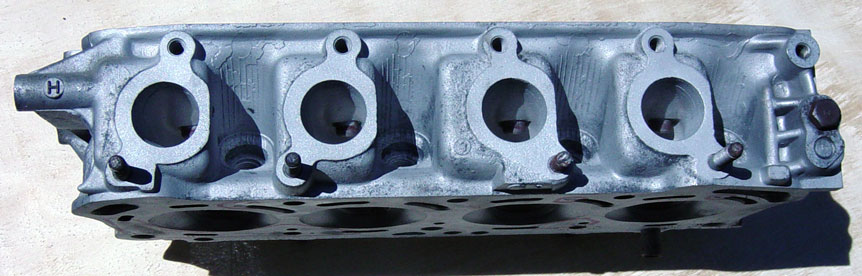
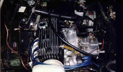
EB3 Head is Identified by the letter "H" stamped on the front left torque
rod mount.
|
|
|
|
|
|
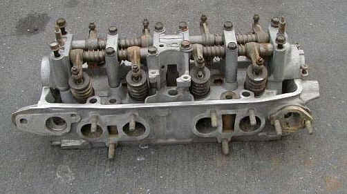
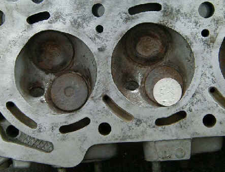
Back of EB3 head
|
Notice Quarter on valve
|
|
|
|
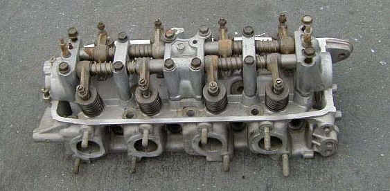
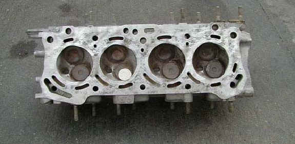
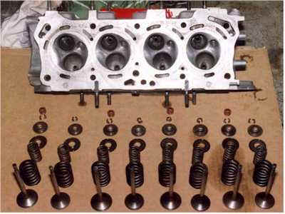
Stripped down EB3
|
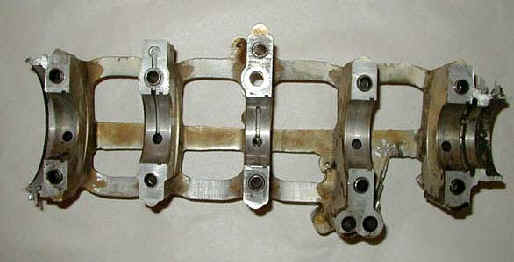
Bearing Cage
|
|
|
|
Angled Distributor
|
|
|
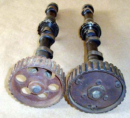
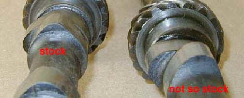
Cam Shaft Stock
|
Cam Shaft Not so Stock
|
|
|
|
Don Foreman's
1.2 cam duration specs
at 1mm lift
|
|
Mugen
R1/MS-1 : btdc 10 - abdc 40 / bbdc 40 - atdc 10
Yoshimura: btdc 15 - abdc 45 / bbdc 45 - atdc 15
|
|
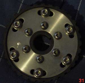
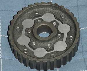
Adjustable Cam Gear 1200
|
Check civic1200.com for a run on these
|
|
|
|
Cam Gear made by Bryan and pictures supplied by Frito at Civic1200.com
|
|
Adjustable cam sprockets give you yet another thing to fiddle with
allowing you to either improve or completely stuff up your engine! At
the simplest level they allow you to ensure that the timing of the cam's
is exactly to specification. It is possible for timing to be out due to
machining tolerances (both in the cams and in the block & head) and
also due to engine rebuilds where the head has been shaved and/or the
block decked.
However it is also possible, through advancing and/or retarding the
cams, to improve the power and flexibility of the engine - although only
up to a point. In a single cam engine, advancing the cam will generally
give an improvement in mid-range power at the cost of some top end. This
is useful for rallying and some tight circuits. Conversely retarding the
cam will give some slight improvement in top end at the cost of
mid-range (sometimes used by drag-racers running into traction
problems). The degree of benefit you obtain also depends on what the cam
grind is to start with. It is possible to have cams ground with some
advance to start with, so further advancing it produces no further mid
range gain but more top end loss.
With twin cam engines, there is even more fun to be had since you can
adjust each cam independently. The general approach is to advance the
inlet cam (to improve mid range at the cost of top end) then retard the
exhaust to try to get back some of what you lost on the top end, but
without losing mid range.
Of course, this type of experimentation must be done with good knowledge
of valve-to-valve-to-piston clearances and cam profiles, otherwise you
risk valves hitting each other and/or the pistons, all of which is
noisy, messy and ultimately expensive!
Generally speaking advancing/retarding a few degrees (say up to 6 or 8
**crankshaft** degrees) will give reasonable results (depending on the
cam grind). Much beyond this tends to result in greater losses but no
more gains in the relevant areas.
Mike S.
|
|
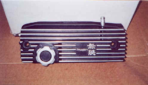
Mugen Valve Cover
|
|
|
|
Pistons
|
|
|
|
EB1 Piston
|
|
|
Piston Upgrades (Venolia)
http://www.venolia.com/imports.html
|
|
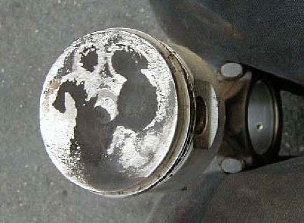
Damaged RS EB1 piston next to an old forged
Venolia 1200 hi compression piston
|
|
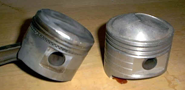 Picture courtesy
of Don Forman
Picture courtesy
of Don Forman
|
|
The pistons I use are for a 73mm bore... but please understand that the
piston mfr. will determine the diameter of the piston and the clearance
requirements. A high performance forged piston will rarely be the same
diameter from dome to skirt, there is usually a bit of a taper due to
thermal mass expansion. I use Venolia's, and they are a great piston.
The Honda Goldwing rings for these pistons, however, are no longer made.
Total Seal has a ring set available, part#6116.040.91-04. This is
assuming a 1.5mm top and middle ring, and a 2.5mm oil control ring. Lemeke
|
|
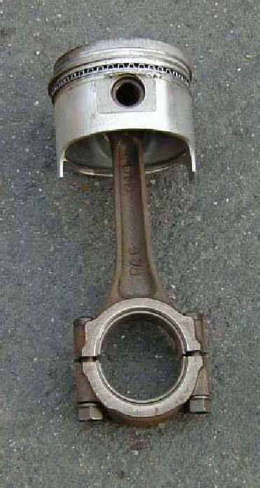
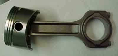
Crower rod and Venolia piston. The rods weigh 32g heavier than stock
|
|
Carburetors
|
|
Dual Dellorto's
|
|
|
|
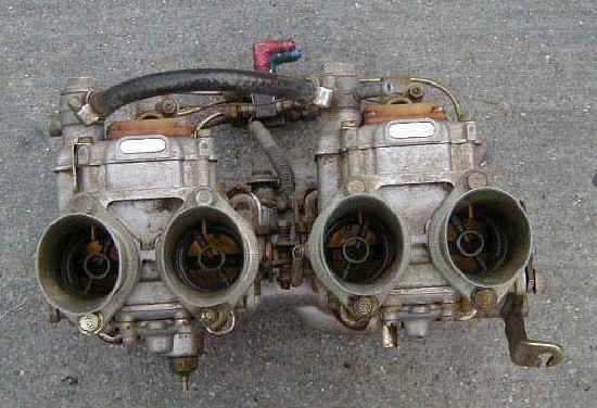
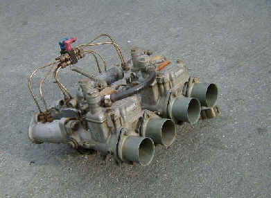
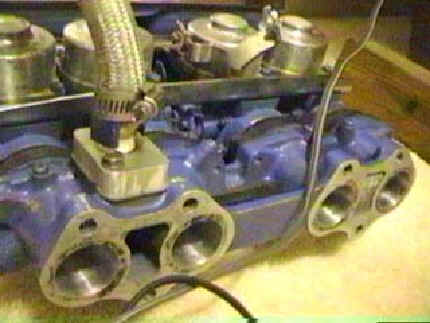
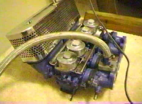
Mugen Quad Side Draft carburetors (from Richard Nasr)
|
|
|
|
Weber Dual 40 DCOE
|
|
|
I run Weber 32/36 DGV's, as do many of the street driven Civics here. The DGV (or
DGEV) stands for something in Italian that means "downdraft". It's basically just like the carburetor you have on your car now, only bigger. The Weber 40 DCOE means "side draft"( again, in Italian). This means that the intake for the air is on the side, as opposed to the top, like the downdrafts (think of the direction the air is traveling through the carburetor). DCOE's tend to be more on the "max power" side of things. Mild and even moderately "built" engines don't really use the capacity these larger carburetors offer. They also require the use of a different intake manifold, which adds to the cost. The numbers in the names are the diameter of the (bores or
venturies, can't recall) in millimeters. So, a 32/36 DGV would translate to: downdraft carburetor, two venturies (barrels), one 32mm, one 36mm. DCOE's are two
venturies, but they only use one number.
The DGV is a manual choke carburetor while the DGEV is a electric
choke carburetor.
|
|
Carburetors by Don
|
|
It depends greatly on how the car is used. A carburetor works on the pressure differential between the outside air and the venturi pressure. If you use a
carburetor that is too big for an application, you do get less restriction that theoretically could give you a minor boost at the very top end of the rpm range. The smaller venturi will out pull the big one in the real world most of the time. 1) because of the greater pressure differential fuel gets atomized better and burns more completely. 2) When you come out of a corner or the light turns green at the drag strip you have a 1500-1800 (You are going to be in the car right?) lbs car with a 100 - 140 hp? then its going to take allot more time to gain rpm than a 600- 800 lbs super bike with the same hp . Rpm = the pressure differential this is why we have some type of enrichment circuit in all
carburetors. 3) The restriction with a side draft
carburetor setup will create a very quick moving air column and this will carry inertia and help fight reversion that you get with a high lift long duration camshaft. I would not recommend the same set up if the air had to make a hard turn like in a down draft set up. I agree that a slide type
carburetor is more forgiving I just think you will better with four 28-32 mm
veturis. Look at the venturi sizes DR Zoom has for the single 40mm Weber on his web. 28-33 for two venturis and you will have FOUR!
You can use what ever
carburetor size you want, but you will not be happy with four 40mm venturi
carburetors unless you don't have anything to compare to.
Bigger is not always better.
|
|
Weber Carburetor Calibration
|
|
Here is the adjustment instructions I got from a guy at redline:
It is important to follow all linkage and lever installation instructions. The number one and two reasons for tuning errors are improper linkage installations and over tightened linkage nut, causing a binding in linkage assembly.
CALIBRATIONS MAY VARY DUE TO REGIONAL FUELS AND STATE OF ENGINE TUNE AND PERFORMANCE. POOR RUNNING QUALITY DOES NOT MEAN A DEFECT IN THE CARBURETOR. AN ADVANTAGE OF THE WEBER CARBURETOR IS ITS EASE OF ADJUSTMENT AND TUNING.
SET UP ADJUSTMENTS
Start set up by confirming carburetor base line settings. Do not depend on the factory delivered settings. Check them before the carburetor is installed.
1. All settings are done with choke disengaged or warmed up so that the choke is fully opened and disengaged. This is done on automatic choke carburetors by first opening the choke butterfly by hand and inserting a wood block or wedge of some kind to hold open while the linkage is cycled (linkage operated through its full movement ) to clear the choke cam. (You will hear a metallic click as the cam is released. You can check the fast Idle screw under the choke assembly to confirm that it is not in contact with the choke fast idle cam.)
2. Set the Idle stop screw (speed screw see fig 1) by backing out the Idle speed screw until it is not in contact with the throttle stop lever. Cycle the linkage again to be sure that the linkage comes to close without any assistance. (Checking for linkage bind) Now bring screw back into contact with the lever and continue to open or screwing in 1 turn no more than 11/2 turns.
3. Set the mixture screw (see Fig 1) by first screwing in until the screw stops, bottoms out. DO NOT FORCE OR BIND AS THIS WILL CAUSE DAMAGE TO THE SCREW AND IT’S SEAT IN THE BODY OF CARBURETOR. Back out the screw 2 full turns.
4. TUNING
BE SURE TO FOLLOW THE NEXT INSTRUCTIONS IN THE PROPER SEQUENCE, DEVIATION WILL CAUSE THE CARBURETOR TO NOT FUNCTION TO ITS IDEAL SPECIFICATIONS AND MAY NOT PROVIDE THE PERFORMANCE AND FUEL ECONOMY AS DESIGNED.
4a. Start the engine, the engine will run very slowly more like a tractor. As long as the engine stays running idle speed is not important at this point.
4b. The first thing to do is not set up the idle speed, but to set the Idle mixture screw to lean best idle setting. First, turn in the mixture screw until the engine dies or runs worse, then back out the screw (recommend turning ¼ to ½ turn at a time). The engine should pick up speed and begin to smooth out. Back out ½ turn more, or until the screw does nothing or runs worse then turn back to the point where it ran its best.
Use your ear, not a scope or tuning instruments at this point. You want to tune the engine by sound. Adjust to best, fastest and smoothest running point.
4c. Now that the mixture screw is at its best running location, you can adjust the Idle speed the screw. The screw will be sensitive and should only take ¼ to ½ turns to achieve the idle speed you like.
Check and set idle to your driving preference. Put the car in gear and apply slight load, (AC on) and set the Idle as you like it. Don’t set it too high, as this will cause causes excessive clutch and brake wear. The Idle only needs to be 7 to 900 RPM with light load or AC on.
5. Recheck timing and vacuum hook ups. Recheck mixture screw to lean best idle again. If all is still best and smoothest idle then confirm and note the final settings.
To confirm settings with the engine running. Start by screwing in the mixture screw and count the number of turns it takes to bottom out and note if the engine dies. If Idle Mixture screws are with in ½ turn of base line setting then all is well and have fun. Also check the speed screw and note how many total turns from initial contact. You may have opened (turned in) the speed screw. Your final setting should be under 2 full turns. Reset the screws (back in) to the best final settings (Per your notes) and go on a test drive and have fun. If the settings are other than described then you may want to recalibrate the Idle circuit (low speed circuit) to your engines needs. This is done by following the rule of thumb BELOW.
Simple Rules for low speed calibration
If the mixture screw is more than 21/2 turns out turns then the Idle jet is too lean (too Small). When the mixture screw is less than 11/2 then the Idle jet is too rich (too large). These assumptions are based on the fact that the speed screw setting is not opened more than 11/2 turns. If the speed screw has to be opened 2 or more turns then this is also an indication of a lean condition usually requiring greater change. At times it may appear to be showing signs of richness or flooding it is really a lean condition. See pictures and notes in the tech 2 article supplied in the kit instructions, view and please understand the need to keep throttle plate as near to closed as possible so as not to prematurely expose the transition holes. This is what causes the visible rich condition, and confirms the need to increase the jet size. JET KITS are available if needed.
EXAMPLE With the speed screw set at no more than two (2) turns in after contact with the stop lever; and the best idle occurring with the mixture screw set at 3 turns from bottom, indicates the need for a larger Idle jet. Achieving the best idle at under 2 turns indicates the need for a smaller idle jet.
The secret to understanding the critical nature of the carburetor set up and the advantages of a WEBER over other carburetors is the Idle circuit. Referred to as the low speed circuit by Weber, this circuit is responsible for 80% of the driving operation. This is the reason that the Weber should give a fuel economy improvement over most factory
carburetors along with significant performance gains. In the worst case you should not see a significant fuel economy loss over stock, while improving HP & Drivability.
|
|
Weber Carburetor Troubleshooting
|
|
|
Weber Carburetors
|
|
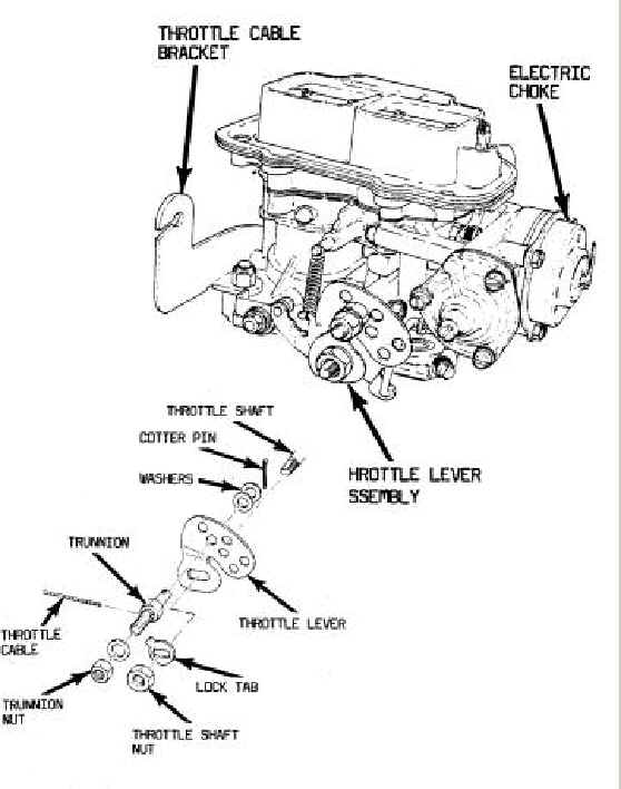 I'm reading from your post that the throttle cable pulls all the way back, but the throttle only opens 2/3 of the way. If that the case, does the throttle open all the way when turned by hand? If so, then the mounting point of the throttle cable onto the throttle lever makes a big difference. In order to get the throttle to open more, you'll need to mount the cable as close to the throttle shaft as you can. Since the arc of rotation is less the closer you get to the throttle shaft, it will open more for the same amount of cable travel. The only thing to watch for is going too close. At that point the throttle won't open anymore and any additional cable travel stresses the throttle shaft. You may have to modify a lever to get it to work. I'm reading from your post that the throttle cable pulls all the way back, but the throttle only opens 2/3 of the way. If that the case, does the throttle open all the way when turned by hand? If so, then the mounting point of the throttle cable onto the throttle lever makes a big difference. In order to get the throttle to open more, you'll need to mount the cable as close to the throttle shaft as you can. Since the arc of rotation is less the closer you get to the throttle shaft, it will open more for the same amount of cable travel. The only thing to watch for is going too close. At that point the throttle won't open anymore and any additional cable travel stresses the throttle shaft. You may have to modify a lever to get it to work.
|
|
 The first thing would be to make sure that most of the slop is taken out of the cable at the throttle cable bracket. You only need a little bit of deflection when the throttle is resting normally (not on the fast idle cam) with the cable hooked to the closest hole to the throttle shaft. If that doesn't give you max opening, you can try drilling the correct size hole in the lever closer to the shaft.
The lever off a stock 1200 carburetor is perfect. It's shaped sort of like the lever in the diagram above except it has a long
arm on the bottom for the return spring. What you do is cut this long arm off. With this setup, you can use the stock cable unmodified. Then you drill a small hole where the are used to be for your throttle return. Much easier than trying to muck about with aftermarket stuff. The first thing would be to make sure that most of the slop is taken out of the cable at the throttle cable bracket. You only need a little bit of deflection when the throttle is resting normally (not on the fast idle cam) with the cable hooked to the closest hole to the throttle shaft. If that doesn't give you max opening, you can try drilling the correct size hole in the lever closer to the shaft.
The lever off a stock 1200 carburetor is perfect. It's shaped sort of like the lever in the diagram above except it has a long
arm on the bottom for the return spring. What you do is cut this long arm off. With this setup, you can use the stock cable unmodified. Then you drill a small hole where the are used to be for your throttle return. Much easier than trying to muck about with aftermarket stuff.
|
|
Weber Install
|
|
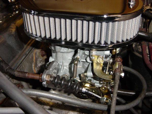 To install the accelerator cable is possibly the only difficult thing about installing a DGV Weber on your old civic. To install the accelerator cable is possibly the only difficult thing about installing a DGV Weber on your old civic.
First get a piece of metal about 1 inch wide by 4 inches long and about 4-5 mm thick. drill a hole in either end about 8mm or so (I am not sure about this).
Then make 2 bends, one about a centimeter above the bottom hole of your choice, and to the right at about a 45 degree angle. then one more about a centimeter below the top hole, so that when the bottom is attached underneath the nearest intake manifold bolt, the top hole is totally facing towards the linkage area. this may need a little adjusting. you may also want to cut a slit a few centimeters wide from the top into the top hole. makes it easier to get the cable in.
The accelerator cable can now be screwed into the hole at the top. there you go. Weber throttle cable bracket for the 1200.
-adapted from an article by Robin Marshall
|
|
Weber Carburetor Adjustments
Carbs Unlimited
Weber
Carbs.com
|